Summarized and extracted from
In image measurement process and machine vision application , In order to determine the relationship between the three-dimensional geometric position of a point on the surface of a space object and its corresponding point in the image , It is necessary to build a geometric model of camera imaging , These geometric model parameters are camera parameters . Under most conditions, these parameters can only be obtained by experiment and calculation , This To solve the parameter ( Internal reference 、 External reference 、 Distortion parameters ) This process is called camera calibration ( Or camera calibration ). Whether it's in image measurement or machine vision applications , The calibration of camera parameters is very important , The accuracy of the calibration results and the stability of the algorithm directly affect the accuracy of the camera results . therefore , Camera calibration is the premise of follow-up work , Improving the calibration accuracy is the key point of scientific research .
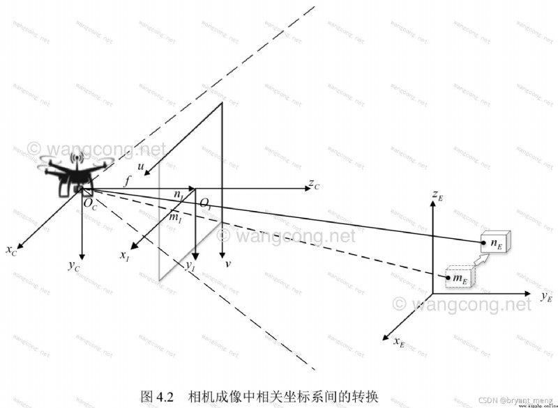
Determining the relationship between the three-dimensional geometric position of a point on the surface of a space object and its corresponding point in the captured image involves the following four coordinate systems
Pixel plane coordinate system ( u , v ) (u,v) (u,v)
Like a plane coordinate system ( Image physical coordinate system ) ( x , y ) (x,y) (x,y)
Camera coordinate system ( X c , Y c , Z c ) (X_c,Y_c,Z_c) (Xc,Yc,Zc),camera coordinate system
World coordinate system ( X w , Y w , Z w ) (X_w,Y_w,Z_w) (Xw,Yw,Zw),world coordinate system (wcs)
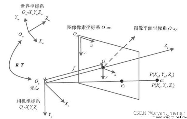
We assume some parameters , Connect the coordinates between the above four coordinate systems , In this way, we can deduce the coordinates of a point on the taken picture from the coordinates of that point in the world coordinate system , In this way, the purpose of three-dimensional reconstruction is achieved .
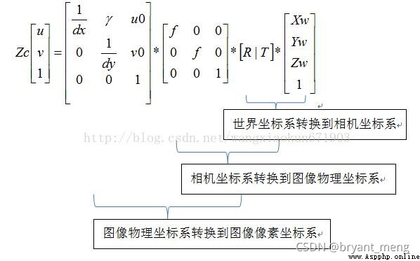
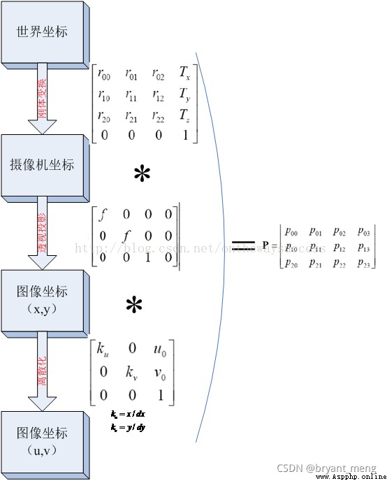
World coordinate system By translation and rotation ( Rigid body transformation ) obtain Camera coordinate system . Camera coordinate system Through the similar triangle principle in the imaging model ( Perspective projection ) obtain Image coordinate system . Image coordinate system By panning and zooming Pixel coordinate system .
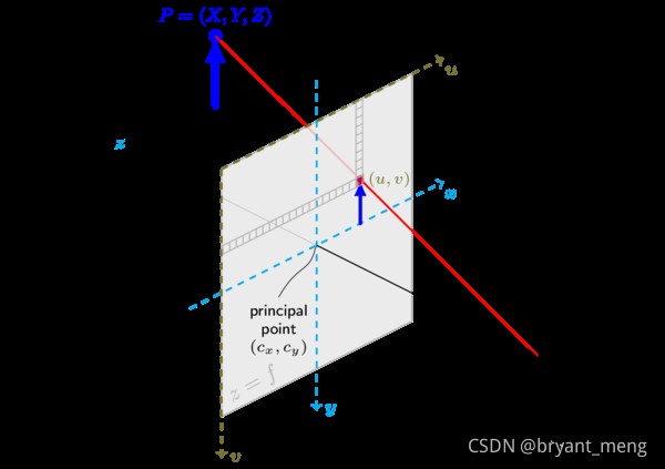
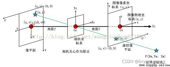
Image physical coordinate system ( x , y ) (x,y ) (x,y): Take the intersection of the camera optical axis and the imaging plane (principal point) It's the origin of the coordinates , Describe the position of the object projected in the imaging plane by projection ( The actual size of pixels on the photosensitive chip ), The unit is usually mm, Belongs to a physical unit .
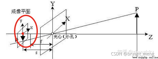
The area circled in red , That is, image physical coordinate system , Red origin , It can be recorded as the origin of the image coordinate system .
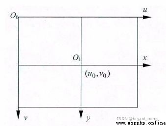
Pixel coordinate system ( u , v ) (u,v ) (u,v): Take the upper left vertex of the imaging plane as the coordinate origin , To describe pixels (pixel) The coordinate position in the digital image is introduced .
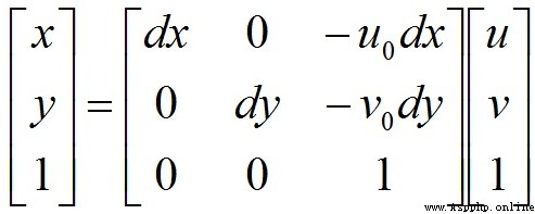
The conversion relationship between image coordinate system and pixel coordinate system is as follows :

In matrix form :
Then write it in homogeneous coordinate form :

among , ( u , v ) (u,v ) (u,v) Indicates the number of rows and columns of pixels , ( u 0 , v 0 ) (u_0,v_0 ) (u0,v0) Represents the coordinates of the origin of the image coordinate system in the pixel coordinate system , d x dx dx and d y dy dy Indicates that a single pixel is in x x x Axis and y y y Physical dimensions on the shaft ( Unit is mm/pixel), thus x d x \frac{x}{dx} dxx And y d y \frac{y}{dy} dyy In pixels .
Of course, we can also express it in the following form
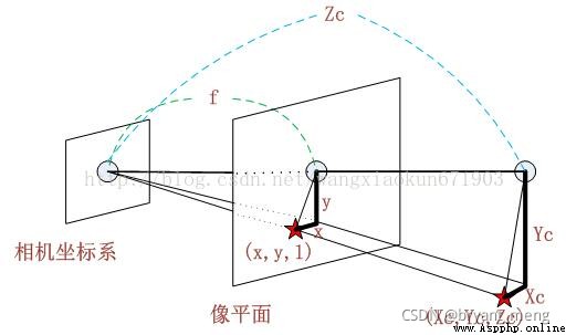
Camera coordinate system ( X c , Y c , Z C ) (X_c,Y_c,Z_C ) (Xc,Yc,ZC): Take the optical center of the camera as the coordinate origin , [ The formula ] The axis is parallel to the optical axis of the camera , Unit is mm
Z c Zc Zc Refers to the image depth information , Every pixel point Z c Zc Zc There will be a difference
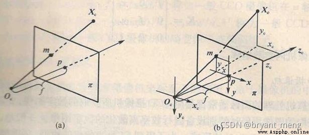
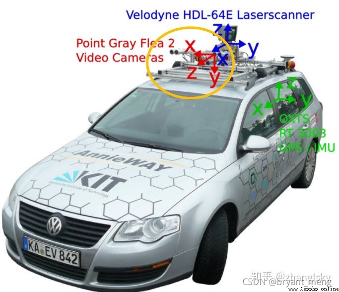
Do you always think that the above pictures deviate from the small hole imaging , Look at these two pictures below, and there will be a bright future , Suddenly it's clear
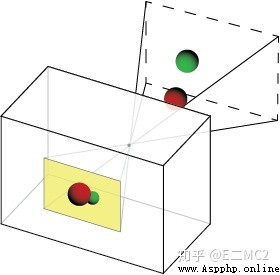
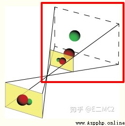
The red box part is
Or draw it directly, which will be much more intuitive
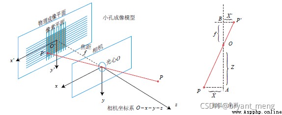
According to the triangle similarity principle :
You can get :
Write in the form of homogeneous coordinate matrix :

Bring the conversion formula between pixel coordinate system and image coordinate system into , Available :

You can get :
among , f x = f d x fx = \frac{f}{dx} fx=dxf , f y = f d y fy = \frac{f}{dy} fy=dyf Respectively means that the camera is x x x Axis and y y y Focal length in the axial direction , Inside the camera (Camera Intrinsic parameter) K K K by :

World coordinate system ( X W , Y W , Z W ) (X_W,Y_W,Z_W ) (XW,YW,ZW):
Because cameras and objects can be placed anywhere in the environment , Therefore, it is necessary to select a reference coordinate system in the environment to describe the position of the camera , And use it to describe the position of any object in the environment , This coordinate system is called World coordinate system .
Want to put different viewpoints / When the image information taken from the perspective is integrated, all the information must be placed in the same coordinate system , This coordinate system should be consistent with the The camera / object / Pixels These relative coordinates are independent , It shall remain unchanged and unique after determination , It should be an absolute coordinate system , We call this coordinate system World coordinate system .
The world coordinate system can be arbitrarily selected , Is an imaginary coordinate system , Immediately after being designated Unchanging and unique , It is the absolute coordinate system
Origin of camera coordinates , It can be any camera position ( As shown in the yellow box below ), Generally, the optical center of the camera is set as the origin of the camera coordinates , In the space Z The axis is parallel to the optical axis of the camera !
The relationship between the world coordinate system and the camera coordinate system is rigid body transformation :

among [ R T 0 1 ] = [ r 11 r 12 r 13 t 1 r 21 r 22 r 23 t 2 r 31 r 32 r 33 t 3 0 0 0 1 ] \begin{bmatrix} R & T\\ 0 & 1 \end{bmatrix} = \begin{bmatrix} r_{11} & r_{12} & r_{13} & t1 \\ r_{21} & r_{22} & r_{23} & t2 \\ r_{31} & r_{32} & r_{33} & t3 \\ 0 & 0 & 0 & 1 \end{bmatrix} [R0T1]=⎣⎢⎢⎡r11r21r310r12r22r320r13r23r330t1t2t31⎦⎥⎥⎤
R、T It has nothing to do with the camera , Therefore, these two parameters are called the external parameters of the camera (extrinsic parameter)
Next, we will introduce the external parameter matrix in detail
Because the world coordinate system and camera coordinate system are both right-hand coordinate systems , So it will not deform . We want to convert the coordinates under the world coordinate system to the coordinates under the camera coordinate , As shown in the figure below , Can pass Rigid body transformation The way . A coordinate system in space , It can always be converted to another coordinate system through rigid body transformation .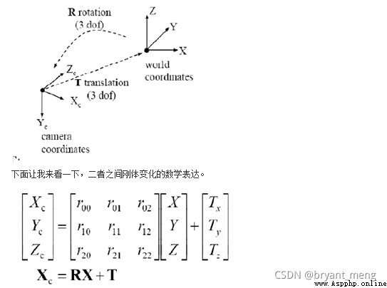
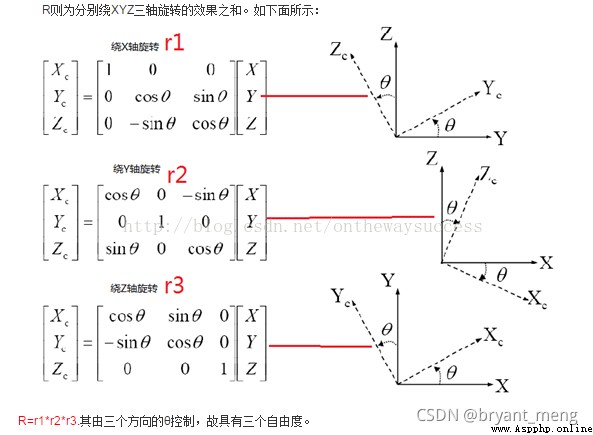
among , X C X_C XC Represents the camera coordinate system , X X X Represents the world coordinate system . R R R For rotation ( Because of it x,y,z The components in three directions are jointly controlled , So it has three degrees of freedom ), T T T Represents translation
In practice , The selection of the world coordinate system can be divided into two cases , Monocular and binocular cameras .
1, Monocular camera
In a monocular camera , We usually choose the camera coordinate system when taking the first image as the world coordinate system , That is, the optical center of the camera when the first image is taken ( Pinhole ) As the origin ,X The axis is horizontal ,Y The axis is vertical ,Z The axis points in the direction the camera looks when taking the first image . Once selected, the world coordinate system will not change , That is, invariant and unique .
2, Binocular camera
In a binocular camera (A,B) in , It is similar to monocular camera , We can choose one of the cameras A The camera coordinate system when the first image is taken is the world coordinate system , That is, with the camera A The optical center of the camera when the first image is taken ( Pinhole ) As the origin ,X The axis is horizontal ,Y The axis is vertical ,Z The axis points to the camera when the first image is taken A The direction of observation .
In this case A Camera's R Is the unit matrix ,T Zero vector
Here is a brief mention of some opencv Library method
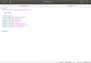
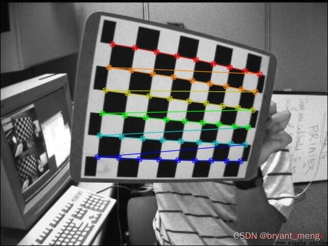
1)findChessboardCorners and drawChessboardCorners
Find the corners of the calibration grid , Note that the input needs to be a grayscale image
import cv2
img = cv2.imread(image)
h, w, _ = img.shape
gray = cv2.cvtColor(img, cv2.COLOR_BGR2GRAY)
ret, corners = cv2.findChessboardCorners(gray,(w,h),None) # Corner finding , w and h Is the number of corners in each row and column of the calibration table
cv2.drawChessboardCorners(img,(w,h), corners, ret) # Draw corners
Reference resources python+OpenCV Camera calibration
2)getAffineTransform
According to the three corresponding points of the two graphs , Find affine transformation matrix 
M = cv2.getAffineTransform(InputArray src, InputArray dst)
3)warpAffine
Transform the image to generate a new image
cv2.warpAffine(src, M, dsize[, dst[, flags[, borderMode[, borderValue]]]]) → dst
Reference resources OpenCV And cv2.getAffineTransform + warpAffine
So let's look at that flags and borderMode What are the options
4) interpolation
Interpolation method ,cv2.xxx opencv Interpolation algorithm in 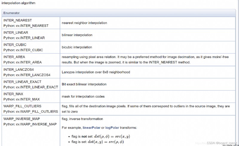
5) fill
Filling method python-opencv Image channel separation , Merge , Boundary extension 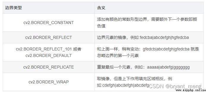
OpenCV Library member ——BorderTypes
 Python bicycle rental system design and implementation report, based on django+mysql, including complete source code
One 、 Project introduction 1.
 [Python automated office] share several popular modules and suggest collecting them
Today, Id like to recommend so