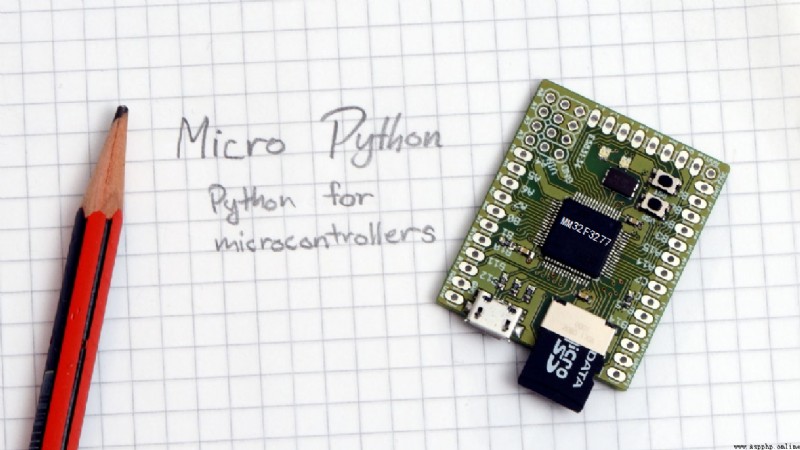
Jane Medium : This paper gives MicroPython Kernel Development Notes : Experimental tasks are embedded in the book Medium SPI Some contents of software use cases .
key word:MicroPython,MM32F3277,SPI
stay MM32F3277 MicroPython Supported by the SPI Including three channels : SPI0、SPI1、SPI2, The following table shows the port resources they occupy .
Through the following applet , It can also be directly passed through REPL Input the following program interactively , Show SPI Related information .
from machine import Pin,SPI
import time
print(SPI(0))
print(SPI(1))
print(SPI(2))
The execution results are as follows , The pin resources of MCU occupied by three channels are given .
SPI(id=0, baudrate=80000000, polarity=0, phase=0), on MOSI(PA7), MISO(PA6), SCK(PA5)
SPI(id=1, baudrate=80000000, polarity=0, phase=0), on MOSI(PB15), MISO(PB14), SCK(PB10)
SPI(id=2, baudrate=80000000, polarity=0, phase=0), on MOSI(PA8), MISO(PB9), SCK(PC9)
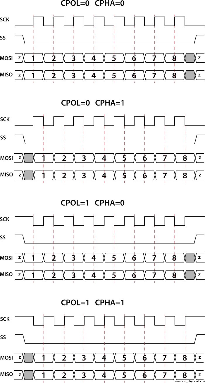
You can see , By default ,SPI The clock frequency of is 8MHz, The polarity and phase modes are 00. Four different clock polarity phase modes correspond SPI The signal is shown in the figure below .
▲ chart 1.1.1 SPI Clock polarity and phase Through the following code , You can see spi Object .
from machine import SPI
spi = SPI(0, baudrate=100000, polarity=1, phase=0)
dir(SPI)
The code output information is :
['read', 'readinto', 'write', 'LSB', 'MSB', 'deinit', 'init', 'write_readinto']
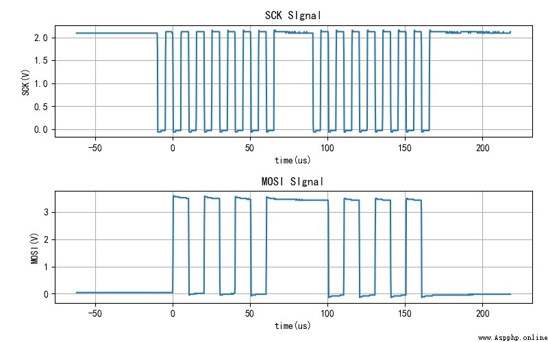
The following code will SPI0 Set to baud rate 100kHz, The clock polarity=1,phase=0. every other 10ms Send byte 0x55,0xaa.spi By function write Output data .
stay PA5(SCK)、PA7(MOSI) measurement SPI0 The output signal .
from machine import Pin,SPI
import time
spi = SPI(0, baudrate=100000, polarity=1, phase=0)
print("Begin to send 0x55aa from SPI0.")
buf = bytes((0x55,0xaa))
while True:
spi.write(buf)
time.sleep_ms(10)
▲ chart 1.1.2 MOSI,SCK Signal waveform because SPI The summary is full duplex bus , That is, sending and receiving can be carried out at the same time . The following code is from SPI The bus reads two bytes , While reading bytes , Output 0x55.
from machine import Pin,SPI
import time
spi = SPI(0, baudrate=100000, polarity=1, phase=0)
print("Begin to read 2 bytes from SPI0.")
buf = bytes((0x55,0xaa))
while True:
data = spi.read(2,0x55)
time.sleep_ms(10)
measurement PA5(SCK)、PA7(MOSI) The signal of two pins . It can be seen from the signal waveform ,SPI Read in function read At the time of execution , Read two bytes and send two bytes at the same time 0x55.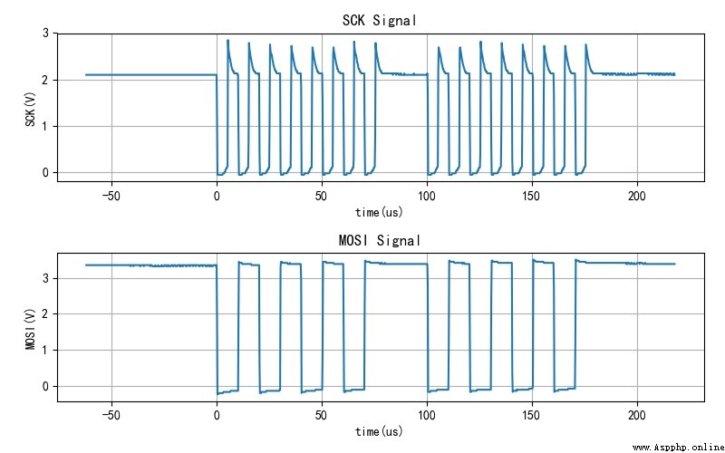
▲ chart 1.1.3 MOSI,SCK Signal waveform stay PLUS-F3270 The experimental board is equipped with a SPI Interface FLASH chip W25Q64 , Connected to the SPI1 On the interface . Use PE3 As the chip selection signal .
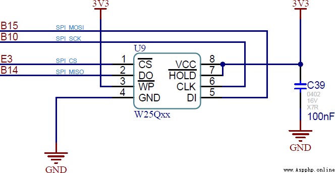
▲ chart 1.2.1 On the experimental board FLASHaccording to W25Q64 From the data book , Passing instructions 0x90,0xab,0x4b You can read the manufacturers separately ID、 device ID、64 Bit unique serial number . The following code demonstrates reading these ID Data method . Used SPI Of write_readinto function , Completed the command sending and data receiving .
from machine import Pin,SPI
import time
W25Q_CE = Pin("PE3", Pin.OUT_PUSHPULL, value=1)
W25Q_SPI = SPI(1, baudrate=8000000, polarity=0, phase=1)
def w25qIO6Bytes(outb,inbs):
outbuf = bytes([outb] + [0]*(inbs-1))
inbuf = bytearray(inbs)
W25Q_CE(0)
W25Q_SPI.write_readinto(outbuf, inbuf)
W25Q_CE(1)
return inbuf
inb = w25qIO6Bytes(0x90,6)
print(list(inb))
inb = w25qIO6Bytes(0xab,5)
print(list(inb))
inb = w25qIO6Bytes(0x4b,13)
print(list(inb))
Here is the result of the code run . contrast W25Q64 Data manual , You can know that the read data is correct .
[255, 255, 255, 255, 239, 23]
[255, 255, 255, 255, 23]
[255, 255, 255, 255, 255, 210, 100, 108, 51, 91, 20, 19, 45]
Here's how to use SPI Yes W25Q64 Read 、 Write 、 Erase function .
def w25qReadData(address, readlen):
inbuf = bytearray(readlen)
W25Q_CE(0)
W25Q_SPI.write(b'\x03' + address.to_bytes(3, 1))
W25Q_SPI.readinto(inbuf, 0x0)
W25Q_CE(1)
return inbuf
def w25qWritePage(address, data):
W25Q_CE(0)
W25Q_SPI.write(b'\x02' + address.to_bytes(3, 1) + data)
W25Q_CE(1)
def w25qWriteEnable():
W25Q_CE(0)
W25Q_SPI.write(b'\x06')
W25Q_CE(1)
def w25qSectorErase(address):
W25Q_CE(0)
W25Q_SPI.write(b'\x20' + address.to_bytes(3, 1))
W25Q_CE(1)
Using the above functions, we can complete the W25Q64 Programming for .
The following is right W25Q64 Read before programming W25Q64 front 16 Bytes of data , All are 0xff, This shows that these addresses can allow new data to be written later .
bytearray(b'\xff\xff\xff\xff\xff\xff\xff\xff\xff\xff\xff\xff\xff\xff\xff\xff')
The following code will 0x0 ~ 0xf write in W25Q64.
w25qWriteEnable()
w25qWritePage(0x0, bytes(list(range(0x10))))
time.sleep_ms(10)
inb = w25qReadData(0, 0x10)
print(inb)
Then before reading 0x10 Data , The results are as follows :
bytearray(b'\x00\x01\x02\x03\x04\x05\x06\x07\x08\t\n\x0b\x0c\r\x0e\x0f')
This paper gives MicroPython Kernel Development Notes : Experimental tasks are embedded in the book Medium SPI Some contents of software use cases .
When SPI Of CLK The polarity of is set to 0, polarity=0 when ,CLK When the signal is static It seems to be high resistance state . The following is the captured signal waveform . You can see in the CLK Waveform baseline exists 50Hz interference signal .
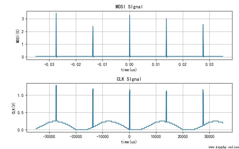
▲ MOSI,CLK Signal waveform however , When polarity=1 when , CLK The signal is at high level , The voltage is stable .
guess : The specific reason is unknown . It seems necessary to CLK The signal line is grounded through the pull-down resistor .
■ Links to related literature :
● Related chart Links :